Structure factor (crystallography)

The structure factor, F, is a function that expresses the sum of amplitudes of scattered X-rays from all atoms in a crystal.

We have, in the previous section, discussed the scattering factor of a single atom, which is the sum of amplitudes of waves scattered by the electrons in the atom. We shall now describe the sum of amplitudes of scattered X-rays from all atoms in a unit cell.

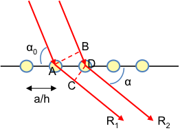
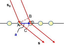
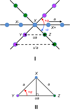
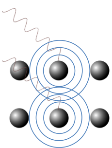
Consider a one-dimensional lattice along the a-axis consisting of two types of atoms (see diagram above). If the Laue equation along the a-axis is satisfied for R1 and R3 as well as for Rand R4, we have:

\delta _{11\: atoms}=\delta _{22\: atoms}=\frac{a}{h}(cos\alpha -cos\alpha _0)=n\lambda

However, if the Laue equation along the -axis is not satisfied for R1 and R2 (or for Rand R3) we have:

\delta _{12\: atoms}=x(cos\alpha -cos\alpha _0)

Combining the two equations above and letting n = 1,

\delta _{12\: atoms}=\frac{\lambda hx}{a}\; \; \; \; \; \; \; (34)

Substitute eq28 in eq34,

\phi =\frac{2\pi hx}{a}\; \; \; \; \; \; \; (35)

Recall from the previous section that the amplitude of the scattered X-ray received by the detector from an atom is equivalent to the scattering factor f=4\pi \int_{0}^{\infty }\rho \frac{sinkr}{kr}r^2dr. If we have two atoms, the resultant amplitude F at the detector is

F=f_1+f_2e^{i\phi }\; \; \; \; \; \; \; (36)

The second term in eq36 includes the factor e  as the scattered rays from the second atom may have a phase difference from that from the first atom. If Φ = 0, Ff1f2 .


Question

Show that the intensity detected from eq36 is consistent with the intensity associated to the resultant amplitude of two general complex waves having a phase difference of Φ.

Answer

Let the waves be y1 = Aei(kx-ωt) and y2 = Bei(kx-ωt+Φ) . The resultant amplitude is y = Aei(kx-ωt) y2 = Bei(kx-ωt+Φ). As we know, the intensity of the resultant wave is proportional to the square of magnitude of the amplitude of the wave:

I\propto\left | y \right |^2=y^*y=\left [ Ae^{-i(kx-\omega t)}+Be^{-i(kx-\omega t+\phi )} \right ]\left [ Ae^{i(kx-\omega t)}+Be^{i(kx-\omega t+\phi )} \right ]

I\propto A^2+ABe^{i\phi }+ABe^{-i\phi}+B^2

Since e^{\pm i\phi}=cos\phi \pm isin\phi

I\propto A^2+B^2+2ABcos\phi

Similarly, for eq36

I \propto (f_1+f_2e^{-i\phi})(f_1+f_2e^{i\phi})

I\propto {f_{1}}^{2}+{f_{2}}^{2}+2 {f_{1}}{f_{2}}cos\phi


Substitute eq35 in eq36,

F=f_1+f_2e^{i\frac{2\pi hx}{a}}\; \; \; \; \; \; \; (37)

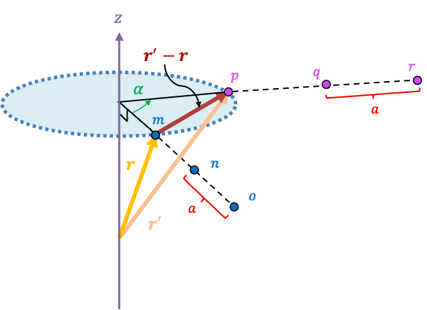
In three dimensions, eq37 becomes

F_{hkl}=f_1+f_2e^{i\frac{2\pi hx_2}{a}}+...+f_je^{i\frac{2\pi hx_j}{a}}+

f_1e^{i\frac{2\pi hy_1}{a}}+f_2e^{i\frac{2\pi hy_2}{a}}+ ...+f_je^{i\frac{2\pi hy_j}{a}}+

f_1e^{i\frac{2\pi hz_1}{a}}+f_2e^{i\frac{2\pi hz_2}{a}}+ ...+f_je^{i\frac{2\pi hz_j}{a}}

So,

F_{hkl}=\sum_{j}f_je^{i2\pi (\frac{hx_j}{a}+\frac{ky_j}{b}+\frac{lz_j}{c})}\; \; \; \; \; \; \; (38)

The first term in eq38 is f_1e^{i\frac{2\pi hx_1}{a}} in one-dimension. Since there is no phase difference between the resultant X-ray of the first atom with itself, f_1e^{i\frac{2\pi hx_1}{a}}=f_1 and eq38 is consistent with eq37, i.e. the phases of scattered X-rays of atoms are relative to that of the first atom at the coordinate of x1 = 0. Eq38 can be rewritten in terms of fractional coordinates:

F_{hkl}=\sum_{j}f_je^{i2\pi ({hx_j}'+{ky_j}'+{lz_j}')}\; \; \; \; \; \; \; (39)

where {x_j}'=\frac{x_j}{a} (i.e. xin units of a), {y_j}'=\frac{y_j}{b}{z_j}'=\frac{z_j}{c}.

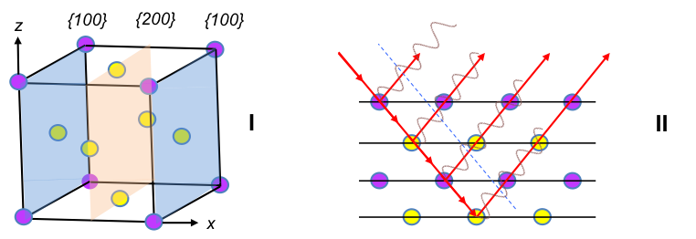
The intensity of a diffraction signal is proportional to the square of the magnitude of the three-dimensional structure factor, i.e. I \propto \left | F_{hkl} \right |^2 and therefore systematic absences appear when F_{hkl}=0.

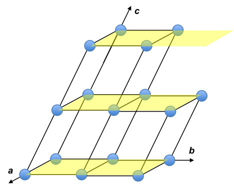
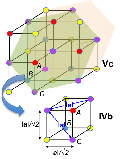
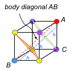
For example, the body centred cubic unit cell (where a = b = c) has fractional coordinates shown in the diagram below.

As the unit cell is composed of the same atoms, the structure factor for each atom is the same. If an atom is shared by m neighbouring unit cells, we multiply the scattering factor of the atom with 1/m. Therefore, eq39 becomes:

F_{hkl}=\frac{1}{8}f[e^{i2\pi (0+0+0)}+e^{i2\pi (0+k+0)}+e^{i2\pi (h+k+0)}+e^{i2\pi (h+0+0)}+

e^{i2\pi (0+0+l)}+e^{i2\pi (0+k+l)}+e^{i2\pi (h+k+l)}+e^{i2\pi (h+0+l)}]+fe^{i2\pi (\frac{h}{2}+\frac{k}{2}+\frac{l}{2})}

Since ei2π = cos2π + isin2π = 1, e = cosπ + isinπ = -1 and eab = (ea)b

F_{hkl}=\frac{1}{8}f[1+1^k+1^{h+k}+1^h+1^l+1^{k+l}+1^{h+k+l}+1^{h+l}]+f(-1^{h+k+l})

Since 1a = 1

F_{hkl}=f[1+(-1^{h+k+l})]

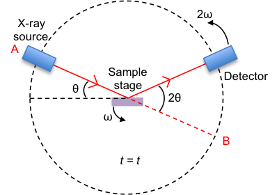
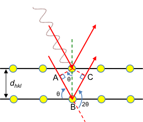
If h + k + l is even, Fhkl = 2f. If h + k + l is odd, Fhkl = 0. Hence, systematic absences occur when h + k + l is odd. A primitive cubic unit cell is different from a BCC in that it does not have an atom at (\frac{1}{2},\frac{1}{2},\frac{1}{2}) . Its structure factor is Fhkl = f, which means the diffraction intensities of a cubic P cell has no restriction other than the scattering factor of the atom, which is dependent on the Bragg’s angle θ and hence Bragg’s law of sin\theta =\frac{\lambda \sqrt{h^2+k^2+l^2}}{2a} .

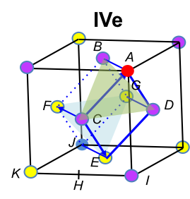
For a face-centred cubic unit cell, the coordinates of the atoms are the same as a cubic P unit cell plus six other atoms on the six faces: (\frac{1}{2},\frac{1}{2},0), (\frac{1}{2},0,\frac{1}{2}), (0,\frac{1}{2},\frac{1}{2}), (\frac{1}{2},\frac{1}{2},1), (\frac{1}{2},1,\frac{1}{2}), (1,\frac{1}{2},\frac{1}{2}). These atoms are each shared by two neighbouring cells. The structure factor of a face-centred cubic unit cell is:

F_{hkl}=f+\frac{1}{2}f[e^{i2\pi (\frac{h}{2}+\frac{k}{2}+0)}+e^{i2\pi (\frac{h}{2}+0+\frac{l}{2})}+e^{i2\pi (0+\frac{k}{2}+\frac{l}{2})}+

e^{i2\pi (\frac{h}{2}+\frac{k}{2}+l)}+e^{i2\pi (\frac{h}{2}+k+\frac{l}{2})}+e^{i2\pi (h+\frac{k}{2}+\frac{l}{2})}]

F_{hkl}=f+\frac{1}{2}f[(-1^{h+k})+(-1^{h+l})+(-1^{k+l})+(-1^{h+k+2l})+

(-1^{h+2k+l})+(-1^{2h+k+l})]

F_{hkl}=f+\frac{1}{2}f[(-1^{h+k})+(-1^{h+l})+(-1^{k+l})+(-1^{h+k})(-1^{2l})+

(-1^{h+l})(-1^{2k})+(-1^{k+l})(-1^{2h})]

F_{hkl}=f+f[(-1^{h+k})+(-1^{h+l})+(-1^{k+l})]

If h, k, l are all even or all odd, Fhkl = 4f. If one index is odd and two are even, or vice versa, Fhkl = 0. Therefore, a face-centred cubic unit cell does not have systematic absences when h, k, l are all even or all odd.


next article: electron density
previous article: scattering factor
Content page of X-ray crystallography
Content page of advanced chemistry
Main content page

Laue equations

The Laue equations are formulated in 1914 by Max Theodor Felix Laue, a German physicist. Like the Bragg equation, they serve to explain X-ray diffraction patterns. 

Consider a one-dimensional row of equally spaced lattice points of a crystal in the diagram above. If \alpha _0\neq \alpha, the path difference δ between R1 and Ris given by

\delta =AC-BD

Since AC=\frac{a}{h}cos\alpha and BD=\frac{a}{h}cos\alpha _0,

\delta =\frac{a}{h}(cos\alpha -cos\alpha _0)

For constructive interference to occur, the path difference must be an integral multiple of the wavelength of the X-ray radiation. So,

a(cos\alpha -cos\alpha _0)=nh\lambda\; \; \; \; \; \; \; (15)

Similarly, for the other two axes of the crystal, we have:

b(cos\beta -cos\beta _0)=nk\lambda\; \; \; \; \; \; \; (16)

c(cos\gamma -cos\gamma _0)=nl\lambda\; \; \; \; \; \; \; (17)

Eq15, eq16 and eq17 are collectively known as the Laue equations. For constructive interference to occur in three dimensions, the three equations must be simultaneously satisfied.

The Laue equations can also be expressed in vector form (see above diagram), where s and s0 are wave vectors of the scattered and incident X-rays respectively; a is the lattice vector along the a-axis. Again,

\delta =AC-BD

Since AC=\left | \textbf{\textit{a}}\right |cosDAC and \textbf{\textit{a}}\cdot\textbf{\textit{s}}=\left | \textbf{\textit{a}}\right |\left | \textbf{\textit{s}}\right |cosDACAC=\textbf{\textit{a}}\cdot \frac{\textbf{\textit{s}}}{\left | \textbf{\textit{s}} \right |}. Similarly, BD=\textbf{\textit{a}}\cdot \frac{\textbf{\textit{s}}_0}{\left | \textbf{\textit{s}} _0\right |}. So,

\delta=\textbf{\textit{a}}\cdot \frac{\textbf{\textit{s}}}{\left | \textbf{\textit{s}} \right |}-\textbf{\textit{a}}\cdot \frac{\textbf{\textit{s}}_0}{\left | \textbf{\textit{s}}_0 \right |}\; \; \; \; \; \; \; (18)

Substituting \left | \textbf{\textit{s}}\right |=\left | \textbf{\textit{s}}_0\right |=\frac{1}{\lambda } (see below for explanation) in eq18,

\delta =\lambda\textbf{\textit{a}}\cdot (\textbf{\textit{s}}-\textbf{\textit{s}}_0)\; \; \; \; \; \; \; (19)

For constructive interference to occur,

\lambda\textbf{\textit{a}}\cdot (\textbf{\textit{s}}-\textbf{\textit{s}}_0)=h\lambda\; \; \; \Rightarrow \; \; \; \textbf{\textit{a}}\cdot (\textbf{\textit{s}}-\textbf{\textit{s}}_0)=h\; \; \; \; \; where\; h\in \mathbb{Z}\; \; \; \; \; \; \; (20)

Similarly, for the other two axes, we have,

\textbf{\textit{b}}\cdot (\textbf{\textit{s}}-\textbf{\textit{s}}_0)=k\; \; \; \; \; where\; k\in \mathbb{Z}\; \; \; \; \; \; \; (21)

\textbf{\textit{c}}\cdot (\textbf{\textit{s}}-\textbf{\textit{s}}_0)=l\; \; \; \; \; where\; l\in \mathbb{Z}\; \; \; \; \; \; \; (22)

Eq20, eq21 and eq22 are the Laue equations in vector form.


Question

Why is \left | \textbf{\textit{s}}\right |=\left | \textbf{\textit{s}}_0\right |=\frac{1}{\lambda } ?

Answer

A wave vector k, like any vector, has a direction and magnitude. Its direction is perpendicular to the wavefront, while its magnitude is defined as the number of waves per unit distance, which is 1/λ. Therefore, \left | s \right |=\left | s_0 \right |=\frac{1}{\lambda}.

Wave vectors and have origins in the de Broglie relation, which is p = h/λ = hk where k = 1/λ. Since p is a vector, k must also be a vector, as h is a constant, i.e. p = hk. This implies that k is also a momentum vector with magnitude of 1/λ.

\left | \textbf{\textit{k}}\right |=\sqrt{\textbf{\textit{k}} \cdot\textbf{\textit{k}}}=\frac{1}{\lambda }

next article: equivalence of the laue equations and the bragg equation
Previous article: systematic absences
Content page of X-ray crystallography
Content page of advanced chemistry
Main content page

Systematic absences

Systematic absences are ‘missing’ diffraction intensities on a powder X-ray diffraction spectrum of intensity versus 2θ. Consider the possible values of h, k and l that satisfy Bragg’s equation of sin\theta = \frac{\lambda \sqrt{h^2+k^2+l^2}}{2a} for a primitive cubic unit cell:

hkl 100 110 111 200 210 211 220 300 221
h+ k+ l2 1 2 3 4 5 6 8 9

9

7 is missing in the h+ k+ l2 sequence, as h, k and l are integers. An extension of the sequence reveals that 15, 23, etc. are missing as well. Hence, the spectrum for a primitive cubic unit cell has a specific set of missing intensities. Likewise, different missing intensity sets are expected for other unit cells. For example, a sample with grains that are composed of face-centred cubic unit cells (figure I below) has scattered rays from {200} planes that are out of phase with rays from {100} (figure II), resulting in destructive interference with no {100} intensity peak on the spectrum.

In fact, for all face-centred cubic unit cells (FCC), intensity peaks are observed when the integers h, k and l are either all odd or all even, e.g. {111}, {200}, {220}, …. A mathematical treatment of this requires the knowledge of the structure factor, which is described in a later section. The structure factor for a body-centred cubic unit cell (BCC) also shows that systematic absences do not appear when k + l = 2n, i.e. when the sum of the Miller indices is even, e.g. {110}, {200}, {211}, ….

Question

Identify the cubic unit cells of polonium and aluminium and determine their dimensions using the following powder X-ray diffraction spectral data:

i 1 2 3 4 5 6 7 8

Po

12.1o 17.1o 21.0o 24.3o 27.2o 29.9o 34.7o

36.9o

Al

38.4 o 44.7 o 65.0 o 78.1 o 82.3 o 98.9 o 111.8 o 116.4 o

λAl = 71.0 pm and λPo = 154.1 pm

Answer

Let’s tabulate the systematic absences of the three cubic unit cells for reference, knowing that i) 7 is missing for a primitive cubic cell, ii) the integers h, k and l for an FCC cell are either all odd or all even, and iii) that h + k + l = 2n for a BCC cell.

hkl 100 110 111 200 210 211 220 300

221

h2k2 + l2

Primitive

1 2 3 4 5 6 8 9

9

BCC

2 4 6 8

FCC

3 4 8

Squaring both sides of eq13, we have

sin^2\theta =\frac{\lambda ^2}{4a^2}(h^2+k^2+l^2)\; \; \; \; \; \; \; (14)

If the unit cell is primitive, the successive ratios of \frac{sin^2\theta _i}{sin^2\theta _1} will produce the sequence 1,2,3,4,5,6,8,9… since from eq14, \frac{sin^2\theta _i}{sin^2\theta _1}=\frac{({h}^{2}+{k}^{2}+{l}^{2})_i}{(h^{2}+{k}^{2}+{{l}^{2})_1}} and {(h^{2}+{k}^{2}+{{l}^{2})_1}}=1. If the unit cell is BCC, we need to multiply the successive ratios of \frac{sin^2\theta _i}{sin^2\theta _1} by the factor 2 to obtain the fingerprint sequence of 2,4,6,8… since {(h^{2}+{k}^{2}+{{l}^{2})_1}}=2. By the same logic, the multiplication factor is 3 if the unit cell is FCC. Tabulating the ratios,


\frac{sin^2\theta _1}{sin^2\theta _1} \frac{sin^2\theta _2}{sin^2\theta _1} \frac{sin^2\theta _3}{sin^2\theta _1} \frac{sin^2\theta _4}{sin^2\theta _1} \frac{sin^2\theta _5}{sin^2\theta _1} \frac{sin^2\theta _6}{sin^2\theta _1} \frac{sin^2\theta _7}{sin^2\theta _1} \frac{sin^2\theta _8}{sin^2\theta _1}

Po

1.00 1.99 2.99 3.99 4.98 5.99 8.01

9.02

Al

1.00 1.34 2.67 3.67 4.00 5.34 6.34

6.68

it is clear that the unit cell for polonium is primitive cubic while that for aluminium is FCC. To verify the fingerprint sequence of an FCC unit cell, we multiply the aluminium ratios by the factor of 3:


\frac{sin^2\theta _1}{sin^2\theta _1} \frac{sin^2\theta _2}{sin^2\theta _1} \frac{sin^2\theta _3}{sin^2\theta _1} \frac{sin^2\theta _4}{sin^2\theta _1} \frac{sin^2\theta _5}{sin^2\theta _1} \frac{sin^2\theta _6}{sin^2\theta _1} \frac{sin^2\theta _7}{sin^2\theta _1} \frac{sin^2\theta _8}{sin^2\theta _1}

Al x3

3.00 4.01 8.01 11.01 12.01 16.01 19.02

20.04

Finally, the dimensions of the unit cell of each sample is obtained by substituting any corresponding set of θ and hkl values in eq14:


a

Po

337 pm

Al

406 pm


As mentioned above, to mathematically show that the integers h, k and l for an FCC cell are either all odd or all even, and that h + k + l = 2n for a BCC cell, we need to explain what the structure factor is. To do this, we must first understand the Laue equations and the scattering factor.


next article: laue equations
Previous article: powder X-ray diffraction
Content page of X-ray crystallography
Content page of advanced chemistry
Main content page

Powder X-ray diffraction

Powder X-ray diffraction is a scientific method for determining the structure of materials. The diagram below shows the main components of a powder X-ray diffractometer.

The substance to be analysed is placed on the sample stage. It is in its powder (or polycrystalline) form, which contains millions of grains of three-dimensional lattices that are randomly orientated in space (see figure II below). Therefore, every possible orientation of every set of lattice plane is present in the sample.

The position of the X-ray source is fixed, while the sample stage is rotated at an angular rate of ω, where ω = dθ/dt. The detector is rotated in the same direction as the sample stage but at an angular rate of 2ω.

Consider the sample stage being parallel to the line AB and the detector at B when t = 0. At t = t, the sample stage makes an angle θ with the incident X-ray vector, while the detector collects scattered or diffracted X-ray that makes an angle of 2θ with the incident X-ray. By convention, the angles of diffraction are recorded at 2θ instead of θ. 

Question

Why does the detector rotate at a higher angular rate than the sample stage?

Answer

With reference to the above diagram depicting the diffractometer, the detector will always point along a line that is parallel to the sample stage if its angular rate of rotation is the same as that of the sample stage. It must rotate at a higher rate than ω for any meaningful detection. The rate 2ω is conventionally used.


If there are sufficient grains with lattice planes parallel to the sample stage at t = t (which is statistically possible due to the presence of millions of randomly orientated grains) and Bragg’s law is satisfied, a diffraction signal is recorded.

Let’s assume that figures III, IV, V show the orientation of three grains of a sample of polonium, which has a primitive cubic unit cell dimension of 337 pm,  at time t = t where 2θ = 12.1o. If Mo X-ray of wavelength 71.0 pm were used, and that figures III, IV and V correspond to the family planes of {100}, {100} and {110} respectively , the only grain that has the required orientation to satisfy Bragg’s law is the one in figure III. This is validated by substituting all the relevant variables in eq13.

Figure IV does not satisfy Bragg’s equation, which requires θ1 = θ2 = θ, i.e. incident ray from the source and the scattered ray received by the detector must make the same angle with a lattice plane. Even though specular angles are observed in figure V, a (110) plane of polonium satisfies Bragg’s equation only if 2θ = 17.1o. This is because the interplanar distance of (110) is different from that of (100) and therefore causes scattered X-rays from adjacent lattice points of (110) planes to interfere destructively at 2θ = 12.1o.

Therefore, only one signal corresponding to the family planes of {100} is observed at 2θ = 12.1o. Using the same logic, signals corresponding to {110}, {111}, {200}, … are recorded at 2θ of 17.1o, 21.0o, 24.3o, …. Finally, a spectrum of intensity versus 2θ is generated by the diffractometer for analysis.


Question

Do the planes (010) and (001) for a primitive cubic system give the same diffraction signal as the (100) plane in powder X-ray diffraction?

Answer

Yes, as the grains are randomly distributed. Since the (010) and (001) planes for a primitive cubic unit cell are equivalent to the reference plane (100) by the symmetry of the lattice, the three planes belong to the same family of planes, denoted by {100}, i.e. the signal from {100} includes scattered X-rays from all these planes. For the purpose of unit cell identification, it is not necessary to distinguish the different planes within the same family of planes.


How do we identify the unit cell and determine its dimensions for an unknown sample using powder X-ray diffraction? Part of the solution requires the understanding of systematic absences, which is described in the next section.


next article: systematic absences
Previous article: bragg’s law
Content page of X-ray crystallography
Content page of advanced chemistry
Main content page

Interplanar distance (crystallography)

The interplanar distance is the perpendicular distance between two adjacent planes of a family of planes.

Consider a family of parallel planes {hkl} with the reference plane shown in the diagram below.

The interplanar distance, dhkl, is given by

\mathit{d_{hkl}}=OD=\frac{a}{h}cos\alpha \; \; \; \Rightarrow \; \; \; cos\alpha =\frac{h}{a}\mathit{d_{hkl}}

Similarly, we have

cos\beta =\frac{k}{b}d_{hkl}

cos\gamma =\frac{l}{c}d_{hkl}

For orthogonal axes, cos2α + cos2β + cos2γ = 1 (see below for proof). So,

(\frac{h}{a})^2{d_{hkl}}^{2}+(\frac{k}{b})^2{d_{hkl}}^{2}+(\frac{l}{c})^2{d_{hkl}}^{2}=1

\frac{1}{{d_{hkl}}^{2}}=\frac{h^2}{a^2}+\frac{k^2}{b^2}+\frac{l^2}{c^2}\; \; \; \; \; \; \; (3)

Eq3 describes the interplanar distance for an orthorhombic unit cell. For a primitive cubic unit cell, a = b = c and eq3 becomes

\frac{1}{{d_{hkl}}^{2}}=\frac{h^2+k^2+l^2}{a^2}\; \; \; \; \; \; \; (4)

The diagram below shows two parallel planes with Miller indices of (110) and (220).


The interplanar distance for (110), i.e. between the orange plane and the origin, is twice of that for (220). If we rewrite (220) as (n1 n1 n0), then d110 = ndn1,n1,n0 , where n = 2. In general, for parallel and equidistant planes,

d_{hkl}=nd_{nh,nk.nl}\; \; \; \; \; \; \; (5)

where \mathbb{Z} and n is called the common factor between planes.

Substituting eq5 in eq3 and eq4, we have:

\frac{1}{{d_{nh,nk,nl}}^{2}}=\frac{(nh)^2}{a^2}+\frac{(nk)^2}{b^2}+\frac{(nl)^2}{c^2}\; \; \; \; \; \; \; (6)

\frac{1}{{d_{nh,nk,nl}}^{2}}=\frac{(nh)^2+(nk)^2+(nl)^2}{a^2}\; \; \; \; \; \; \; (7)


Question

Show that cos2α + cos2β + cos2γ = 1 for orthogonal axes.

Answer

With reference to the diagram below,

cos\alpha =\frac{a}{\left | N \right |}\; \; \;\; \; \; \; cos\beta =\frac{b}{\left | N \right |}\; \; \; \; \; \; \; cos\gamma =\frac{c}{\left | N \right |}

cos^2\alpha +cos^2\beta +cos^2\gamma =(\frac{a}{\left | N \right |})^2+(\frac{b}{\left | N \right |})^2+(\frac{c}{\left | N \right |})^2

Since a2 + b2 + c2 = INI2

cos^2\alpha +cos^2\beta +cos^2\gamma =1


next article: bragg’s law
Previous article: miller indices
Content page of X-ray crystallography
Content page of advanced chemistry
Main content page

Crystallographic restriction theorem

The crystallographic restriction theorem generally states that the rotational symmetries of a crystal are limited.

We have seen from a previous section that a lattice is formed by repeating lattice points that have the same environment. It is this fundamental geometric property of a lattice that restricts the number of rotational symmetries of a space lattice and hence the types of unit cells.

To illustrate the crystallographic restriction theorem, let’s consider a row of lattice points (indicated by the line connecting blue dots in figure I of the below diagram) that are equally spaced by the basis vector  a.

Assuming that the lattice has a rotational symmetry given by the angle \alpha, a rotation about the lattice point X by +\alpha, around an axis perpendicular to the plane of this page, maps the blue lattice point X- to the pink lattice point Y. Similarly, a rotation about the same lattice point X by \alpha maps the blue lattice point X+ to the green lattice point Z.

Since the rotations are symmetry operations, Y and Z are also lattice points. As mentioned in an earlier article, the lattice points in a two-dimensional lattice are described by the position vector r = ua + vb where u, v ∈ \mathbb{Z}. Therefore, YZ must be a lattice vector separated by an integer multiple of a, i.e. YZ = ua + 0b or YZ = ua, where u ∈ \mathbb{Z} . With reference to figure II of the above diagram,

cos\alpha =\frac{u\textbf{\textit{a}/2}}{\textbf{\textit{a}}}=\frac{u}{2}\; \; \; \; \; \; \; (4)

Since -1 ≤ cos\alpha ≤ 1,

-1\leq \frac{u}{2}\leq 1\; \; \; \; \Rightarrow \; \; \; \;-2\leq u\leq 2\; \; \; \;u\in \mathbb{Z}\; \; \; \; \; \; \; (5)

Substituting eq5 in eq4, the possible values of \alpha are 180o, 120o, 90o, 60o, 0o (or 360o). As we have assumed that a rotation of the lattice by the angle \alpha transforms the lattice into a state that is indistinguishable from the starting state, the possible values of \alpha correspond to 2-, 3-, 4-, 6- and 1-fold symmetry of the two-dimensional lattice.

For a space lattice in three dimensions, consider a three-dimensional lattice vector r = ua + vb + wc that is neither parallel nor perpendicular to the axis of rotation (see diagram below). A rotation by \alpha maps r onto another lattice vector r’ that has the same magnitude as r. Since both r and r’ are lattice vectors, their difference r’r is also a lattice vector, which lies on a plane that is perpendicular to the axis of rotation.

By varying the integers u, v and w, we can extend m to a row of points mno that are spaced \vert \boldsymbol{\mathit{r'}}-\boldsymbol{\mathit{r}}\vert=a apart. This reduces a three-dimensional lattice proof of the crystallographic restriction theorem to a two-dimensional one, which is already given above.

We have proven the crystallographic restriction theorem with trigonometry. The proof can also be made with linear algebra (see this article).


next article: Bravais lattice (2d)
Previous article: Fractional coordinates
Content page of X-ray crystallography
Content page of advanced chemistry
Main content page

Bragg’s law (crystallography)

Bragg’s law states that the incidence and scattered waves in x-ray diffraction make the same angle with a lattice plane.

X-ray is a form of electromagnetic radiation, which has an alternating electric field component. When a beam of X-rays encounters a charged particle, such as an electron in an atom, its rapidly alternating electric field causes the electron to oscillate and form a dipole. Since an accelerated charge emits electromagnetic radiation, the accelerated electron (sinusoidal change of velocity with time) reemits X-ray at the same frequency as the incident radiation. This phenomenon is known as scattering.

X-ray diffraction is a technique that relies on the interference of X-rays, which are scattered by atoms in a crystal, for analysing properties of the crystal. As the overall electron density of an atom is approximately spherical, X-ray scattered by the atom is consequently spherical (see diagram below). This is analogous to the atoms being the source of spherical wavelets, as stated in Huygens’ principle. The scattered X-rays therefore interfere with one another to form a distinct pattern.

In 1913, William Bragg and his son Lawrence Bragg considered the specular waves scattered by atoms in a crystal, i.e., incident and scattered waves that make the same angle with a lattice plane (see diagram below). They proposed that scattered specular X-ray waves, from atoms separated by an interplanar distance dhkl, interfere constructively when the difference between their respective total path lengths, which is AB + BC, is an integer multiple of the wavelength of the X-ray.

AB=BC=d_{hkl}sin\theta \; \; \; \; \; \; \Rightarrow \; \; \; \; \; \; AB+BC=2d_{hkl}sin\theta

So, according to Bragg’s law:

2d_{hkl}sin\theta =n\lambda \; \; \; \; \; \; \; (10)

where n ∈ \mathbb{Z} and n is called the order of diffraction.

Since both the order of diffraction and the common factor between planes are integers, we can substitute eq5 where dhkl = ndnh,nk,nl in eq10:

2d_{nh,nk,nl}sin\theta =\lambda \; \; \; \; \; \; \; (11)

Combining eq7 where \frac{1}{{d_{nh,nk,nl}}^{2}}=\frac{(nh)^2+(nk)^2+(nl)^2}{a^2}  for a primitive cubic unit cell and eq11, we have:

sin\theta =\frac{\lambda \sqrt{(nh)^2+(nk)^2+(nl)^2}}{2a}\; \; \; \; \; \; \; (12)

where n is now the common factor between planes.

This eliminates the need to describe a signal in terms of the order of diffraction. In other words, each signal now refers to the first order diffraction from the (nh nk nl) plane. Eq12 is often written simply as:

sin\theta =\frac{\lambda \sqrt{h^2+k^2+l^2}}{2a}\; \; \; \; \; \; \; (13)

because it is understood that h = nh, k = nk and l = nl.

The significance of eq12 and eq13 is that a set of lattice planes, with a specific Miller index (hkl) in a solid composed of a particular unit cell dimension, scatters X-rays that interfere constructively at a specific specular angle. Therefore, eq12 and similar equations for other unit cell types allow us to determine unit cell dimensions, if the angle of diffraction and the Miller index (hkl) are known. This is accomplished experimentally via X-ray diffraction techniques, one of which is powder X-ray diffraction.


Question

What if we consider a scattered X-ray vector in a different direction with respect to the one used in Bragg’s law, e.g. one that points below the lattice plane?

Answer

You get a different constructive interference (diffraction) formula known as the Laue equations, i.e., you have a different mathematical approach using different criteria to describe the same diffraction pattern.


next article: Powder X-ray diffraction
Previous article: interplanar distance
Content page of X-ray crystallography
Content page of advanced chemistry
Main content page

Miller indices (crystallography)

The Miller index is a system developed by British mineralogist William Miller in 1839 for describing the orientation of lattice planes. Since a normal vector to a plane describes the orientation or direction of the plane, the Miller index of a plane must have parameters consistent with the normal vector. Recall that the scalar equation of a plane is given by eq2 of the previous section:

\frac{x}{D/A}+\frac{y}{D/B}+\frac{z}{D/C}=1

In the case of a space lattice, let’s rewrite it as:

\frac{x}{a/h}+\frac{y}{b/k}+\frac{z}{c/l}=1

where a/h, b/k and c/l are the intercepts of the plane with the x-axis, y-axis and z-axis respectively, and h, k, l are by definition, integers.

In the diagram above, the plane intercepts the x-axis, y-axis and z-axis at a, b/2 and ∞c respectively. Hence,

\frac{a}{h}=a\; \; \; \Rightarrow \; \; \; h=1

\frac{b}{k}=\frac{b}{2}\; \; \; \Rightarrow \; \; \; k=2

\frac{c}{l}=\infty\: c\; \; \; \Rightarrow \; \; \; l=0

The variables h, k, l are called the Miller indices and are used to describe the orientation of planes via the notation (hkl).

The plane, in this case, is (120). If we draw a position vector that is perpendicular to the plane (depicted as the purple arrow in the diagram), we can describe the vector with the direction [120], which is consistent with the Miller index of the plane. Furthermore, the Miller index of a plane may contain negative numbers, e.g. (1 -2 0) which is denoted by \left ( 1\bar{2}0 \right ).

Consider a crystal with monoclinic unit cells. Due to the periodic arrangement of lattice points, we can find many different planes intersecting the points. The diagram below depicts parallel planes with the middle one having the Miller index of (001) and the top plane of (00½). As whole numbers are preferred in the (hkl) notation, (00½) is rewritten as (001) by multiplying each of the three numbers by the smallest integer that will give whole numbers.

If we shift the origin from the far left lattice point of the bottom layer to the far left lattice point of the middle layer, the top plane becomes (001) and the bottom plane becomes (00\bar{1}). Furthermore, the parallel planes are equivalent by a rotation of the lattice and form a family of planes. In general, we denote the set of all planes that are equivalent to a particular reference plane (hkl) by the symmetry of the lattice as {hkl}. Therefore, we describe this family of planes as {001}. This example shows that the Miller notation does not require axes to be orthogonal to each other.


Question

Can we denote the family of planes in the above diagram as \left \{ 00\bar{1} \right \}?

Answer

Yes. However, the convention is to select the plane that is closest to the origin that has positive indices as the reference plane for the family. Hence, the notation {001} is preferred.

next article: interplanar distance
Previous article: equation of a plane
Content page of X-ray crystallography
Content page of advanced chemistry
Main content page

Bravais lattice 2D (crystallography)

A Bravais lattice has lattice points with the same environment such that the lattice has at least one of the rotational symmetries predicted by the crystallographic restriction theorem. In other words, lattices are Bravais lattices only if they meet the symmetry and ‘same environment’ criteria. Such lattices have patterns depicted in figures I to V in the diagram below.

Notice that a lattice with one-fold rotational symmetry is not included among the two-dimensional Bravais lattices. The reason is as follows:

The purpose of defining two-dimensional Bravais lattices is to use them as a foundation for constructing three-dimensional Bravais lattices and their associated unit cells, which are ultimately of interest to chemists. Since there are many possible lattices with one-fold rotational symmetry in two dimensions, it is more practical to utilise the five specified two-dimensional lattices to develop all possible unit cells, including those that can replicate to form lattices with one-fold rotational symmetry (see the next few articles for details).


Question

Why is the honeycomb lattice (figure VI) not a Bravais lattice?

Answer

Even though the honeycomb lattice satisfies the rotational symmetry criterion, not all lattice points have the same environment. An easy way to determine whether all lattice points have the same environment is to see if their nearest neighbours are in the same directions. With reference to the diagram above, lattice point 1 of figure VI has nearest neighbours in the northeast, northwest and south directions, while lattice point 2 has nearest neighbours in the southeast, southwest and north directions. The honeycomb lattice fails the ‘same environment’ criterion and therefore is not a Bravais lattice. Nonetheless, we can demarcate a unit cell for the lattice by combining two lattice points to establish a single basis (shaded pink). This method of pairing lattice points to form unit cells is commonly used in ionic crystals to determine their lattice types.


next article: Bravais lattice (3d)
Previous article: crystallographic restriction theorem
Content page of X-ray crystallography
Content page of advanced chemistry
Main content page

Proof for distance between lattice layers


Question 1

Show that the triple hexagonal lattice (Vc) becomes a cubic P lattice when the perpendicular distance between two layer of lattices, h, is(IaI√6)/6.

Answer 1

The diagram below shows two layers of the triple hexagonal lattice Vc.

Focusing on just one segment of the space lattice (IVb), IaI refers to the separation between two same-layer lattice points of Vc and is also the surface diagonal of IVb. The body diagonal AB of IVb is determined using Pythagoras’ theorem as follows:

Each side of the cubic P unit cell is IaI/√2 and

(AB)^{2}=(BC)^{2}+(AC)^{2}

AB=\sqrt{\left | \textbf{\textit{a}}\right |^{2}+(\frac{\left |\textbf{\textit{a}} \right |}{\sqrt{2}})^{2}}\; =\left | \textbf{\textit{a}}\right |\sqrt{\frac{3}{2}}

Furthermore, AB is thrice the perpendicular distance between two layers of the triple hexagonal lattice Vc (see below diagram, which is IVb rotated for a better view). 

Since AB = 3h,

h=\frac{\left |\textbf{\textit{a}} \right |}{3}\sqrt{\frac{3}{2}}=\frac{\left | \textbf{\textit{a}}\right |\sqrt{6}}{6}


Question 2

Show that the triple hexagonal lattice (Vc) becomes a cubic F lattice when the perpendicular distance between two layer of lattices, h, is(IaI√6)/3.

Answer 2

Similar to the cubic P unit cell, IaI refers to the separation between two same-layer lattice points of Vc in the cubic F unit cell, e.g. the length of BC. Using Pythagoras’ theorem,

(CE)^{2}=(CH)^{2}+(HE)^{2}

By the symmetry of the cubic F unit cell, BC = CE = IaI and CH = HE. Therefore, CH = IaI/√2 and hence, AI = 2IaI/√2. Furthermore,

(AJ)^{2}=(AI)^{2}+(IJ)^{2}

Since (IJ)= (KI)+ (KJ)2 = (AI)+ (AI)2 = 2(AI)= 4IaI2,

AJ=\sqrt{\left ( \frac{2\left | \textbf{\textit{a}}\right |}{\sqrt{2}} \right )^{2}+4\left | \textbf{\textit{a}}\right |^{2}}=\left | \textbf{\textit{a}}\right |\sqrt{6}

Just like the cubic P unit cell, the body diagonal AJ of the cubic F unit cell (IVe) is thrice the perpendicular distance between two layers of Vc. Therefore,

h=\frac{\left | \textbf{\textit{a}}\right |\sqrt{6}}{3}


Next article: equation of a plane
Previous article: cubic
Content page of X-ray crystallography
Content page of advanced chemistry
Main content page
Mono Quiz