Maxwell’s third equation (or Faraday’s law of electromagnetic induction) states that a time-varying magnetic field induces a circulating electric field.
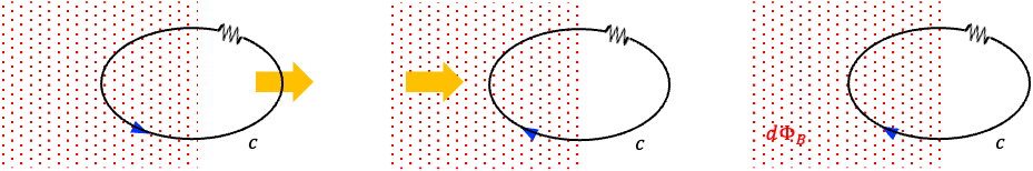
This law originated from the experiments of Michael Faraday in the 1830s. As illustrated in the figure above, Faraday observed that an electromotive force (emf) is induced in a conducting loop
whenever the magnetic flux
through the loop changes. In one experiment, a current was produced when the loop was moved relative to a stationary magnetic field. In another, the same effect occurred when the magnetic field was moved while the loop remained fixed. Faraday also found that a current could be induced even when both the loop and the magnet were stationary, provided that the strength of the magnetic field varied with time. These observations led him to conclude that electromagnetic induction depends not on the absolute motion of the magnet or conductor, but on the rate of change of magnetic flux through the circuit. Quantitatively, the emf is proportional to the rate of change of magnetic flux,
Subsequently, Heinrich Lenz determined the direction of the induced emf. Lenz showed that the induced current always produces a magnetic field that opposes the change in magnetic flux responsible for its creation, consistent with the conservation of energy. This introduces a minus sign into Faraday’s law, giving
Here,
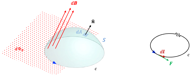
where is an oriented open surface bounded by the conducting loop (often visualised as a “dome” spanning the loop),
is the magnetic field, and
is the infinitesimal area vector associated with a surface element
, with
denoting the unit normal to the surface (see diagram below).
Combining eq20 and eq21 yields
To relate Faraday’s experimental law to the electric field , consider a charge
moving through an infinitesimal displacement
along the wire (see diagram above). The electric force acting on the charge is
. Therefore, the infinitesimal work done
by the electric field on the charge is
Since electric potential difference is defined as the work done per unit charge, , it follows that
The total emf around the loop is obtained by summing these infinitesimal potential differences over the entire closed path . In the limit of infinitely small segments, this becomes the line integral
Thus, the emf induced in the loop is equal to the circulation of the electric field around the closed path. Substituting this result into eq22 gives
where the time derivative may be moved inside the integral because the surface is assumed to be stationary.
This is the integral form of Maxwell’s third equation. To obtain the differential form, we apply Stokes’ theorem, which gives
Since this relation must hold for any arbitrary surface , the integrands in the second equality must be equal at every point:
This is Maxwell’s third equation in differential form. It states that a changing magnetic field generates an electric field whose field lines form closed loops around the region where the magnetic field is changing. Together with Maxwell’s fourth equation, it explains electromagnetic wave propagation.

Question
Why does (called the curl of
) describe a circulating electric field?
Answer
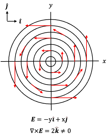
We have determined earlier that the induced emf in the loop is equal to the circulation of the electric field around the closed path . Circulating electric field lines are often illustrated using the vector function
, or equivalently
(see diagram below), where the field vectors are tangent to circles around the origin and point anticlockwise. For example,
points upwards at
,
points left at
,
points downwards at
, and
points right at
. Since the curl of
is given by
it is non-zero and points in the positive -direction. By the right-hand rule, this corresponds to positive (anticlockwise) circulation of the field in the
-plane.