Microwave spectroscopy is a powerful analytical technique that analyses the rotational transitions of molecules. Operating in the microwave region of the electromagnetic spectrum, this method provides highly precise information about molecular structure, bond lengths, bond angles, and even the distribution of electrons within a molecule.

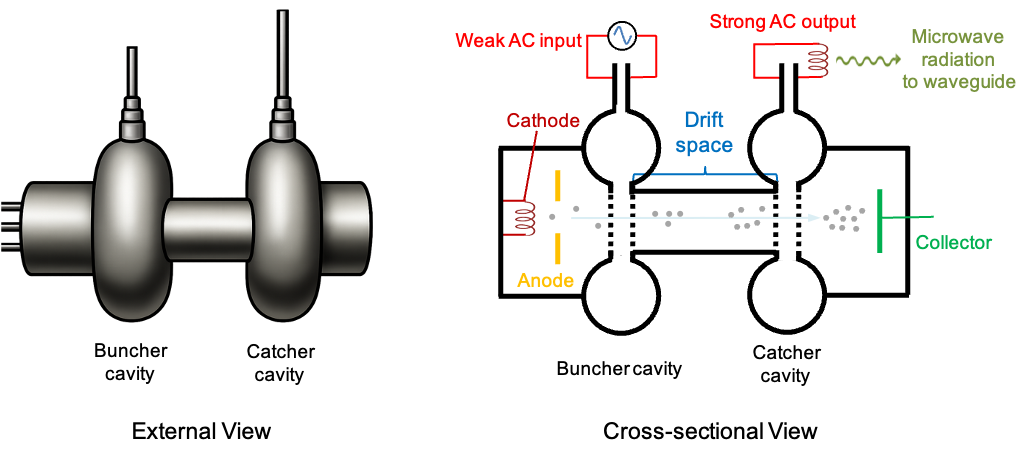
The diagram above outlines a conventional microwave spectrometer. A stable and tunable microwave source is essential for probing molecular energy transitions. This is fulfilled by a device known as a Klystron amplifier, which is a vacuum tube engineered to generate and amplify narrow-band microwave signals that can be precisely tuned to the desired frequency. It was invented in 1937 by American electrical engineers Russell and Sigurd Varian.

A Klystron amplifier includes an electron gun, two resonant cavities (buncher and catcher), a drift tube and a collector (see diagram above). The electron gun operates on the principle of thermionic emission, where electrons are emitted from a heated coil (cathode) and accelerated towards an anode. The buncher cavity is connected to a weak external AC supply (with frequency in the microwave range), which creates an oscillating flow of free electrons within the cavity walls. This, in turn, generates an alternating electric field across the perforated section (grid) of the cavity.
As electrons pass through the grid, they are either accelerated or decelerated depending on the polarity of the electric field. When the entrance grid is negative and the exit grid is positive, electrons are accelerated. When the polarity reverses, they are decelerated. This periodic acceleration and deceleration causes the electrons to bunch together as they travel through the drift tube, forming dense clusters that correspond to the frequency of the external AC source.
When these bunched electrons enter the catcher cavity, they induce a stronger alternating current (due to their higher density) at the same frequency as the AC input. Through an inductor, this energy is converted into strong monochromatic microwave radiation, which is then propagated along a waveguide.

Question
Is the frequency of the generated microwave radiation tunable? How does induction occur in the catcher cavity?
Answer
The resonant cavities are precisely engineered in both shape and size to resonate at a narrow band of microwave frequencies. Each Klystron amplifier module has a narrow operational bandwidth that can be tuned by mechanically adjusting the cavity dimensions using tuning screws. To cover a wider frequency range, multiple modules with different cavity dimensions must be employed.
Electromagnetic theory states that a flowing current generates a magnetic field, and that a changing magnetic field induces an alternating current in a conductor. The varying density of electrons flowing through the catcher cavity constitutes a varying current, which in turn creates a time-varying magnetic field. This results in the induction of an alternating current within the cavity walls.
The waveguide, constructed using copper of stainless steel, is a hollow evacuated tube designed to confine and direct the microwaves to the sample cell, which is often a section of the waveguide. Gases to be analysed are introduced via a gas inlet system, and the cell is often equipped with pumps and valves to control pressure and flush previous samples.
If the monochromatic microwave radiation matches the energy of a specific rotational transition of the molecules, a portion of it will be absorbed by the sample. The remaining (transmitted) microwave signal then reaches the detector, which typically consists of an inductive pickup (antenna), a diode rectifier, capacitors, and an amplifier. The inductor acts as an antenna that couples the microwave radiation into an alternating current (AC), which is then rectified by the diode to produce a pulsating direct current (DC) signal. A low-pass filter, often just a capacitor, smooths the rectified signal into a more stable DC voltage. This process is repeated as the microwave frequency is swept or incremented across a range. At each frequency step, the resulting DC voltage, which is proportional to the transmitted microwave intensity, is amplified and sent to a computer for data acquisition and analysis. Finally, the amplitudes of the DC voltages are plotted as a function of frequency, producing a microwave absorption spectrum that reveals the rotational transitions of the sample.