Raman spectroscopy relies on a compact yet sophisticated set of instruments designed to probe molecular rovibrational states through photon-matter interactions.

The laser provides monochromatic, coherent and intense light required to induce Raman scattering. Common laser types include diode lasers, Nd:YAG lasers and argon-ion lasers, operating at wavelengths ranging from the ultraviolet to the near-infrared region. The sample compartment is designed to accommodate solids, liquids or gases with minimal preparation. Raman instruments may use backscattering (180°), right-angle (90°) or forward-scattering geometries, depending on the application. In the above diagram, scattered radiation perpendicular to the laser beam is focused onto a pinhole.
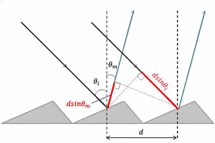
The pinhole acts as a spatial filter that controls the amount of light arriving at the detector and helps define the resolution of the final spectrum. After passing through the slit, the scattered radiation still contains a mixture of Rayleigh, Stokes and anti-Stokes frequencies and is therefore dispersed into its individual wavelength components using a reflective diffraction grating. Each groove on the grating acts as a secondary source of light, generating spherical wavefronts in accordance with Huygen’s principle. Neighbouring reflected wavefronts interfere with one another to produce constructive diffraction patterns as defined by:
where
is the order of the diffraction (with the detector typically positioned to record
).
is the wavelength of the light.
is the spacing between the grooves.
is the angle between the incident ray and grating’s normal vector.
is the angle between the diffracted ray and grating’s normal vector.

Question
Derive eq3.
Answer
With respect to the above diagram, the difference in path length between two adjacent incident rays is , and that between two adjacent diffracted rays is
. Since the incident ray and the diffracted ray are on opposite sides of the normal, the total path difference is
, assuming that both angles are positive. This difference must be an integer multiple of the light’s wavelength for constructive interference to occur. Therefore,
.
Since the groove spacing is fixed, each wavelength is diffracted at a unique angle, causing light reflected from different grooves to travel slightly different path lengths. Constructive interference occurs when these wavefronts arrive in phase, producing intensity maxima at specific angles, while destructive interference reduces or cancels the signal at other angles. This process results in the spatial separation of wavelengths at the focal plane of the instrument.
A charge-coupled device (CCD) is positioned at this focal plane to detect the dispersed light. Its location is precisely calculated to receive the first-order () diffracted rays. The CCD consists of a two-dimensional array of light-sensitive pixels fabricated on a silicon substrate and is widely used due to its high sensitivity, low-noise quality, and ability to simultaneously record a broad spectral range. When photons strike a pixel, they are absorbed by the silicon, generating electron–hole pairs via the photoelectric effect. The number of electrons produced is proportional to the intensity of the incident light. Because each wavelength is focused onto a distinct position on the detector, individual pixels record the intensity corresponding to a single Raman frequency, yielding the final spectrum of intensity
versus frequency (or versus Raman shift
).