Activation polarisation is the change in electrode potential from its equilibrium value when a current flows, as a result of overcoming the activation energy of the rate-determining step in an electrochemical reaction.

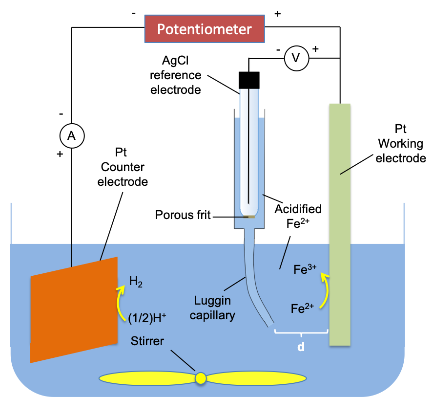
To understand the concept of activation polarisation, let’s analyse an experiment with the following electrode reaction:

where rred is defined as the flow of the number of moles of Ox per unit area of the electrode per unit time, i.e. the rate of reduction of Ox, and rox is the flow of the number of moles of Red per unit area of the electrode per unit time, i.e. the rate of oxidation of Red. We represent rred and rox with the following rate equations:
![r_{red}=k_c[Ox]\; \; \; \; \; \; \; \; 36](https://latex.codecogs.com/gif.latex?r_{red}=k_c[Ox]\;&space;\;&space;\;&space;\;&space;\;&space;\;&space;\;&space;\;&space;36)
![r_{ox}=k_a[Red]\; \; \; \; \; \; \; \; 37](https://latex.codecogs.com/gif.latex?r_{ox}=k_a[Red]\;&space;\;&space;\;&space;\;&space;\;&space;\;&space;\;&space;\;&space;37)
where kc and ka are the cathodic rate constant and anodic rate constant respectively (each with units of length per time). From the combined Faraday’s laws of electrolysis, we have
\;&space;\;&space;\Rightarrow&space;\;&space;\;&space;zF\frac{m}{M}=It\;&space;\;&space;\Rightarrow&space;\;&space;\;&space;zF\frac{no.\:&space;of\:&space;moles}{t}=I\;&space;\;&space;\;&space;\;&space;\;&space;\;&space;\;&space;\;&space;38)
Divide eq38 throughout by the area of electrode,

where j = I/A, is the current density. With reference to eq35, z = 1, and so we can rewrite eq36 and eq37 as:
![j_c=Fk_c[Ox]\; \; \; \; \; \; \; \; 40](https://latex.codecogs.com/gif.latex?j_c=Fk_c[Ox]\;&space;\;&space;\;&space;\;&space;\;&space;\;&space;\;&space;\;&space;40)
![j_a=Fk_a[Red]\; \; \; \; \; \; \; \; 41](https://latex.codecogs.com/gif.latex?j_a=Fk_a[Red]\;&space;\;&space;\;&space;\;&space;\;&space;\;&space;\;&space;\;&space;41)
where jc and ja are the cathodic current density and the anodic current density respectively.

To apply the above equations, consider a piece of metal M immersed in an M+ solution. Over time, an electric double layer is formed, with the development of an equilibrium electrode potential between the metal and its ionic solution, such that rred = rox or jc = ja (i.e. no net current flowing). If we connect the M+/M half-cell to an SHE, the circuit is closed.
Assuming that M lies below hydrogen in the electrochemical series, a net current flows towards the SHE, i.e. electrons flow towards M, the cathode. This results in a less positive electrode reduction potential and the equilibrium in eq35 shifting to the right, with rred > rox. Since the electrode potential deviates from its equilibrium value when a current flows, we say that the electrode is polarised.
In terms of current density, jc is no longer equal to ja, and because it is a reduction reaction, jc > ja, i.e. a net cathodic current flows. The net current density j is given by:
![j=j_a-j_c=Fk_a[Red]-FK_c[Ox]\; \; \; \; \; \; \; \; 42](https://latex.codecogs.com/gif.latex?j=j_a-j_c=Fk_a[Red]-FK_c[Ox]\;&space;\;&space;\;&space;\;&space;\;&space;\;&space;\;&space;\;&space;42)

Question
Why is the net current density ja – jc and not jc – ja?
Answer
This is to be consistent with IUPAC’s definition that a net anodic current is positive, while a net cathodic current is negative (as mentioned above, the current is cathodic when jc > ja, which makes j < 0).
Substituting the Eyring equation  where
where  is the activation Gibbs energy in eq42,
![j=FA_a\left [ Red \right ]e^{-\frac{\Delta ^{\ddagger'}G_a}{RT}}-FA_c\left [ Ox \right ]e^{-\frac{\Delta ^{\ddagger'}G_c}{RT}}\; \; \; \; \; \; \; \; 43](https://latex.codecogs.com/gif.latex?j=FA_a\left&space;[&space;Red&space;\right&space;]e^{-\frac{\Delta&space;^{\ddagger'}G_a}{RT}}-FA_c\left&space;[&space;Ox&space;\right&space;]e^{-\frac{\Delta&space;^{\ddagger'}G_c}{RT}}\;&space;\;&space;\;&space;\;&space;\;&space;\;&space;\;&space;\;&space;43)
with
![j_a=FA_a\left [ Red \right ]e^{-\frac{\Delta ^{\ddagger'}G_a}{RT}}\; \; \; \; \; \; \; \; 44](https://latex.codecogs.com/gif.latex?j_a=FA_a\left&space;[&space;Red&space;\right&space;]e^{-\frac{\Delta&space;^{\ddagger'}G_a}{RT}}\;&space;\;&space;\;&space;\;&space;\;&space;\;&space;\;&space;\;&space;44)
![j_c=FA_c\left [ Ox \right ]e^{-\frac{\Delta ^{\ddagger'}G_c}{RT}}\; \; \; \; \; \; \; \; 45](https://latex.codecogs.com/gif.latex?j_c=FA_c\left&space;[&space;Ox&space;\right&space;]e^{-\frac{\Delta&space;^{\ddagger'}G_c}{RT}}\;&space;\;&space;\;&space;\;&space;\;&space;\;&space;\;&space;\;&space;45)
When the electrode is at equilibrium, ja = jc and we can rewrite eq44 and eq45 as:
![j_0=FA_a[Red]e^{-\frac{\Delta ^\ddagger G_a}{RT}}\; \; \; \; \; \; \; \; 46](https://latex.codecogs.com/gif.latex?j_0=FA_a[Red]e^{-\frac{\Delta&space;^\ddagger&space;G_a}{RT}}\;&space;\;&space;\;&space;\;&space;\;&space;\;&space;\;&space;\;&space;46)
![j_0=FA_c[Ox]e^{-\frac{\Delta ^\ddagger G_c}{RT}}\; \; \; \; \; \; \; \; 47](https://latex.codecogs.com/gif.latex?j_0=FA_c[Ox]e^{-\frac{\Delta&space;^\ddagger&space;G_c}{RT}}\;&space;\;&space;\;&space;\;&space;\;&space;\;&space;\;&space;\;&space;47)
where j0 denotes the equal current densities at equilibrium and is called the exchange current density; and  and
and  are the anodic activation Gibbs energy at equilibrium and the cathodic activation Gibbs energy at equilibrium respectively.
Next, we shall investigate the energy profile of the reaction of eq35 at the cathode at equilibrium (see Fig I below). For simplicity, we assume that the transition state has equal resemblance to M+ and M and therefore the activation Gibbs energy required for the reduction reaction is the same as that of the oxidation reaction.
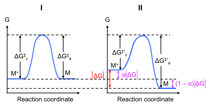
As mentioned, when the electrode is connected to an SHE, its potential becomes less positive, which in turn causes a decrease of the activation Gibbs energy for the reduction reaction (electrode has stronger attraction for M+) and an increase in the activation Gibbs energy for the oxidation reaction (more difficult for M+ to form). The resultant energy profile is shown in Fig II. Note that the peaks in Fig I and Fig II are aligned at the same Gibbs energy level for convenience.
Question
Use eq44 and eq45 to justify the change in activation Gibbs energies for the reduction and oxidation reaction at the cathode when a current flows
Answer
When a cathodic current flows, jc > ja, i.e. cathodic current density level increases versus that at equilibrium. Assuming that the electrolyte is well stirred such that [Ox] remains constant,  in eq45 must decrease. Simultaneously, the reduction in anodic current density at the same electrode results in an increase in
  (see eq44 where [Red] is constant, as it is a solid).
By letting  be the magnitude of the total change in Gibbs energy between the state when a current flows and the state when the electrode is at equilibrium, we have:

\left&space;|&space;\Delta&space;G&space;\right&space;|\;&space;\;&space;\;&space;\;&space;\;&space;\;&space;\;&space;\;&space;49)
where  is a fraction of and is called the transfer coefficient. If you recall, the formula
  is derived based on the definition of the reversible electrical work between two points in a circuit with a potential difference E. The change in Gibbs energy in our case is due to the change in electrode potential when a current flows, E – Eeqm and so, we have:
\;&space;\;&space;\;&space;\;&space;\;&space;\;&space;\;&space;\;&space;50)
Substituting eq34 from the previous article in eq50, the magnitude of the change in Gibbs energy for the passage of one mole of electrons (n = 1) is:

Substituting eq51 in eq48 and eq49,

F\eta\;&space;\;&space;\;&space;\;&space;\;&space;\;&space;\;&space;\;&space;53)
Substituting eq53 and eq52 in eq44 and eq45 respectively,
![j_a=FA_a[Red]e^{-\frac{\Delta^\ddagger G_a}{RT}}e^{\frac{(1-\alpha)F\eta}{RT}}\; \; \; \; \; \; \; \; 54](https://latex.codecogs.com/gif.latex?j_a=FA_a[Red]e^{-\frac{\Delta^\ddagger&space;G_a}{RT}}e^{\frac{(1-\alpha)F\eta}{RT}}\;&space;\;&space;\;&space;\;&space;\;&space;\;&space;\;&space;\;&space;54)
![j_c=FA_c[Ox]e^{-\frac{\Delta^\ddagger G_c}{RT}}e^{\frac{-\alpha F\eta}{RT}}\; \; \; \; \; \; \; \; 55](https://latex.codecogs.com/gif.latex?j_c=FA_c[Ox]e^{-\frac{\Delta^\ddagger&space;G_c}{RT}}e^{\frac{-\alpha&space;F\eta}{RT}}\;&space;\;&space;\;&space;\;&space;\;&space;\;&space;\;&space;\;&space;55)
Substituting eq46 and eq47 in eq54 and eq55 respectively,
f\eta}\;&space;\;&space;\;&space;\;&space;\;&space;\;&space;\;&space;\;&space;56)

where f = F/RT
The net current density is obtained by substituting eq56 and eq57 in eq42:
![j=j_0\left [ e^{\left ( 1-\alpha \right )f\eta}- e^{-\alpha f\eta}\right ]\; \; \; \; \; \; \; \; 58](https://latex.codecogs.com/gif.latex?j=j_0\left&space;[&space;e^{\left&space;(&space;1-\alpha&space;\right&space;)f\eta}-&space;e^{-\alpha&space;f\eta}\right&space;]\;&space;\;&space;\;&space;\;&space;\;&space;\;&space;\;&space;\;&space;58)
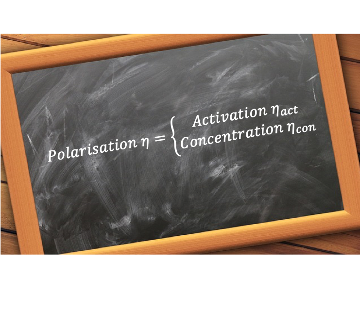
Eq58 is known as the Butler-Volmer equation. If the experiment that we have described so far consists of an electrolyte that is well stirred (so that mass transfer effects are minimised, i.e. no concentration polarisation), the polarisation of the electrode arising from the flow of current is attributed entirely to the change in activation energies of the reduction and oxidation reactions at the electrode, i.e. activation polarisation. Since η is a measure of activation polarisation, η in eq58 is ηact,cat, the activation overpotential at the cathode. Note that ηact,cat < 0 , because η = E – Eeqm where E decreases at the cathode upon polarisation.
If M is more electropositive than hydrogen, it becomes the anode when connected to the SHE. The flow of electrons away from M results in a less negative electrode reduction potential. Using the same logic, we arrive at eq58 with η being ηact,an, the activation overpotential at the anode, where ηact,an > 0.
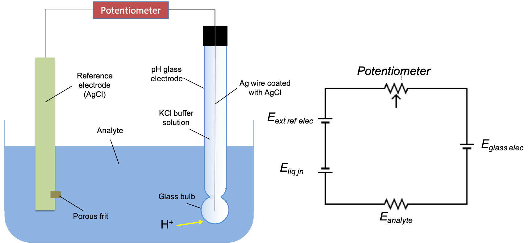
In general, for the electrochemical cell  (see this article for notation),
-\left&space;(&space;E_L+\eta_L&space;\right&space;)=E_{cell,open}+\eta_R-\eta_L\;&space;\;&space;\;&space;\;\;&space;59)
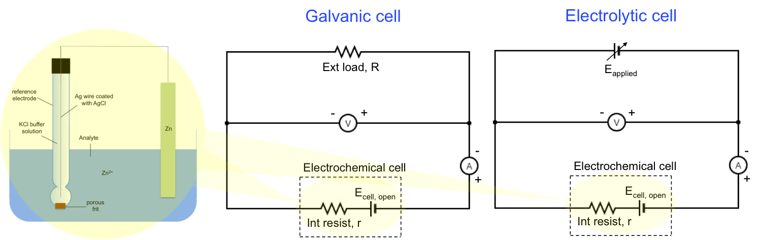
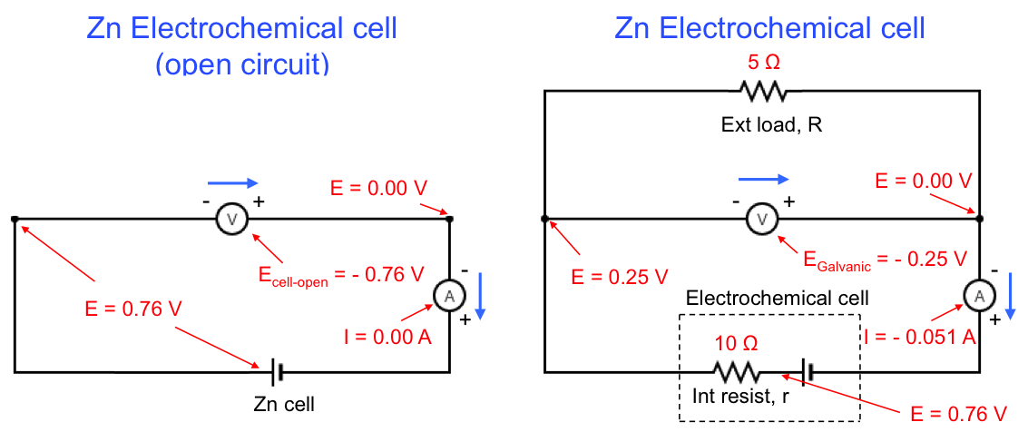
where Ecell, open is the open-circuit potential of the cell at equilibrium, which is usually the standard electrode potential of the cell, E0. Since ηR < 0 and ηL > 0, we can rewrite eq59 as:

where  . Eq60 shows that the relationship of Egalvanic < Ecell,open is always true when a current flows in an electrochemical cell.
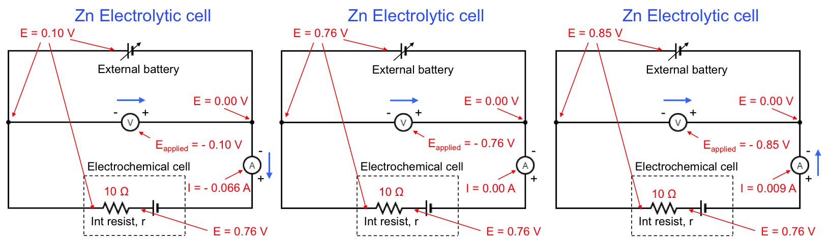
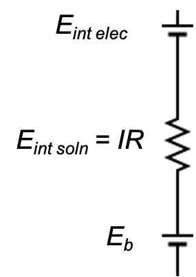
For an electrolytic cell, Ecell,open is usually negative. If we also consider IR drop, the magnitude of the externally applied potential must be greater than the sum of the magnitudes of the cell open-circuit potential, potential due to IR drop and the overpotential, for electrolysis to proceed: